Neural Chip Design [3/4: RTL Design & Verification]
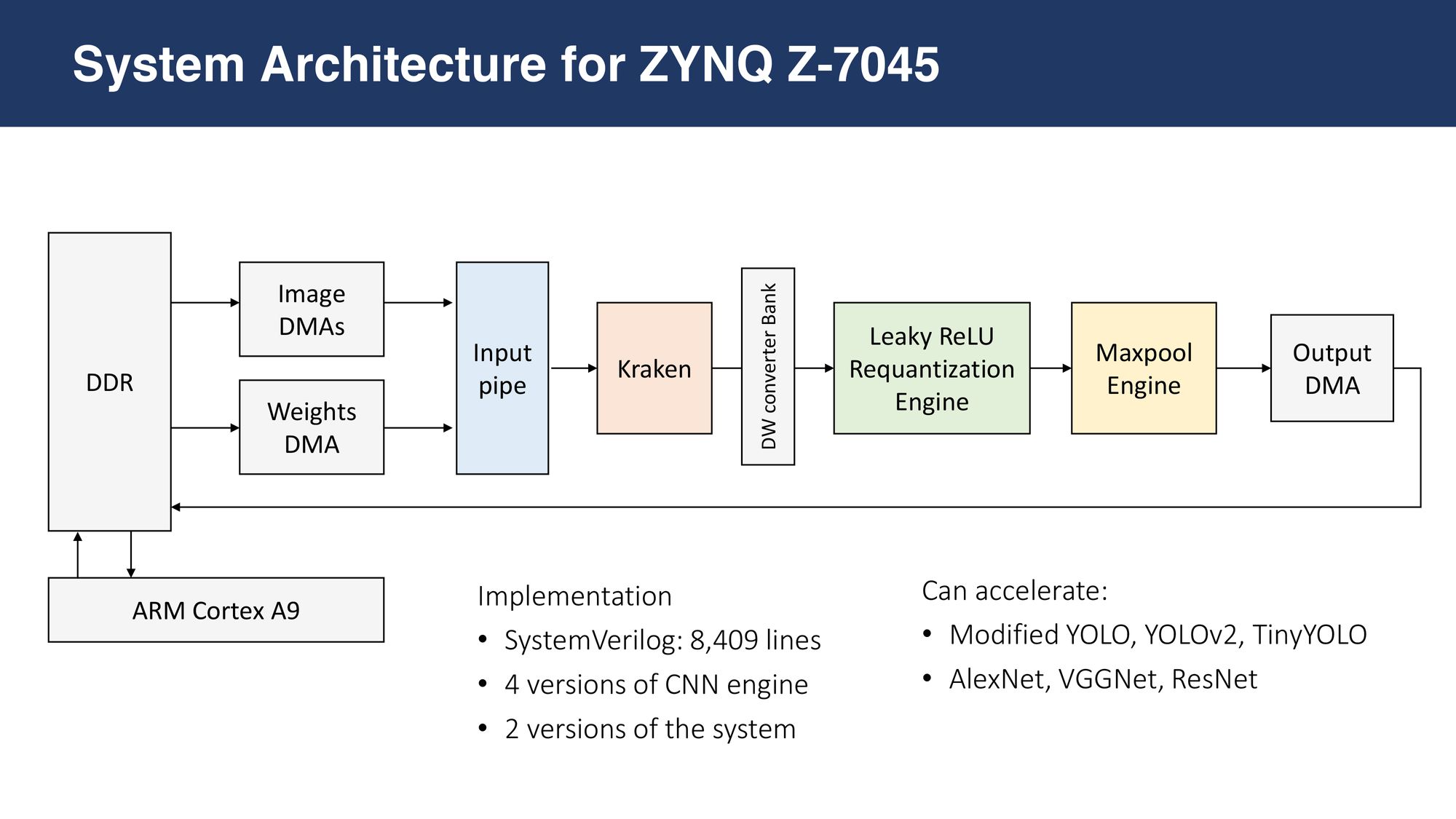
This is a series of articles [overview] outlining the workflow of 15 steps, which I developed over the past few years through building my own DNN accelerator: Kraken [arXiv paper].
After building golden models and understanding the operations, its time to design and implement digital circuits that can accelerate those operations with:
- low on-chip area
- high fmax (hence short critical paths)
- minimal multiplexers, registers, and SRAM usage
For this, I first design my modules in detail, on a whiteboard. I spend days or weeks doing this: optimizing designs and mapping out state machines for each module. Once I'm satisfied. I sit with VSCode and start writing synthesizable RTL. Once I'm done, I generate test vectors from the golden model, write testbenches to read and compare them and start debugging.
Steps:
- Whiteboard: Design hardware
- RTL Design: SystemVerilog/Verilog for the whiteboard designs
- Generate Test Vectors: using Python Notebooks
- Testbenches: SystemVerilog OOP testbenches to read the input vector (txt file), randomly control the valid & ready signals and get output vectors (txt files)
- Debug: Python notebooks to compare the expected output with simulation output and to find which dimensions have errors.
- Microsoft Excel: I manually simulate the values in wires with excel to debug
- Repeat 3-8: For every module & every level of integration
- ASIC Synthesis
3. Whiteboard
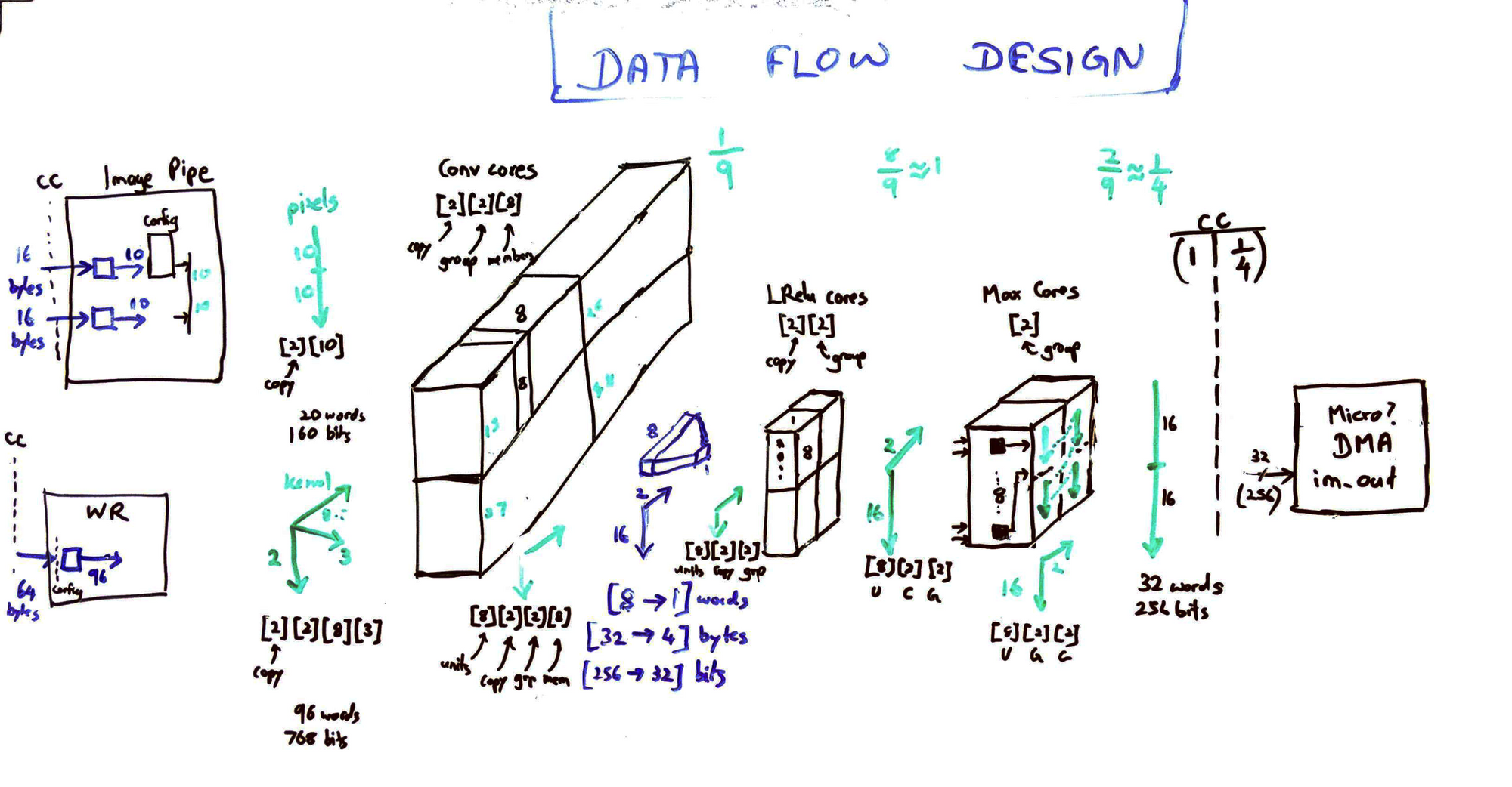
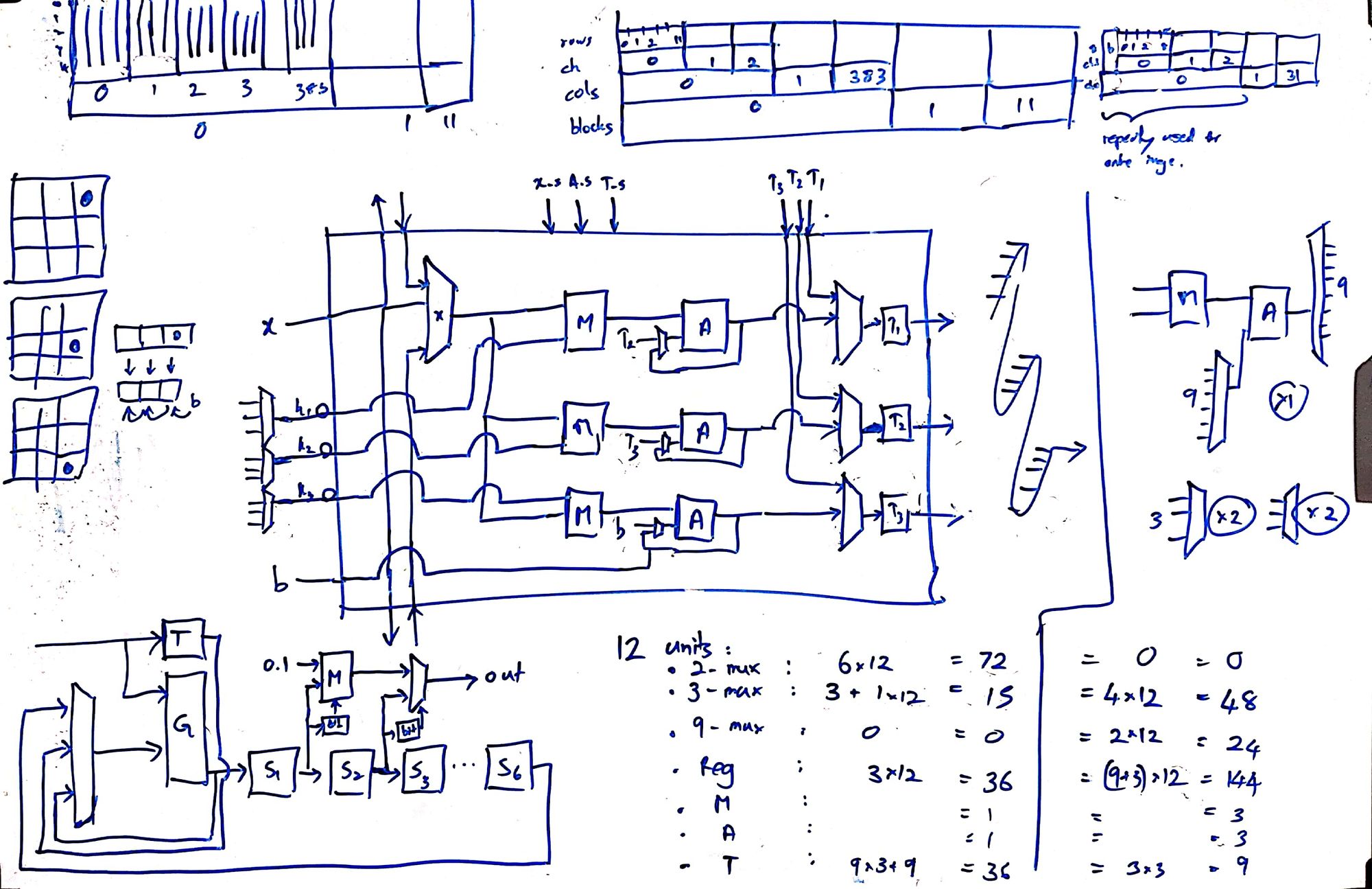
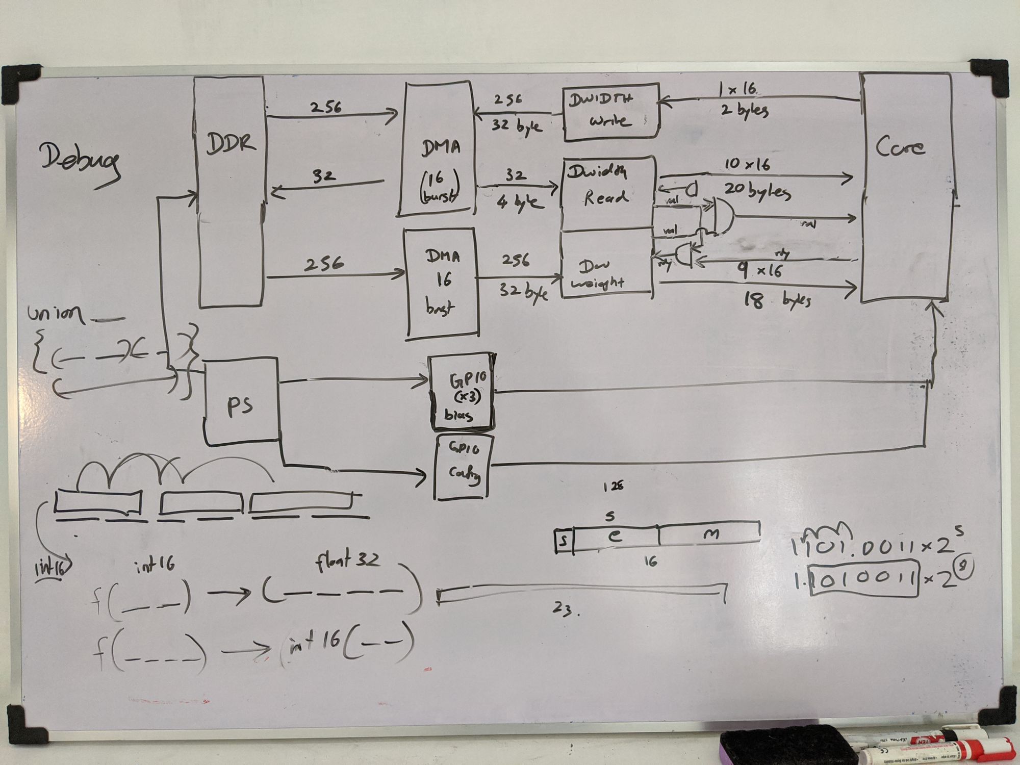
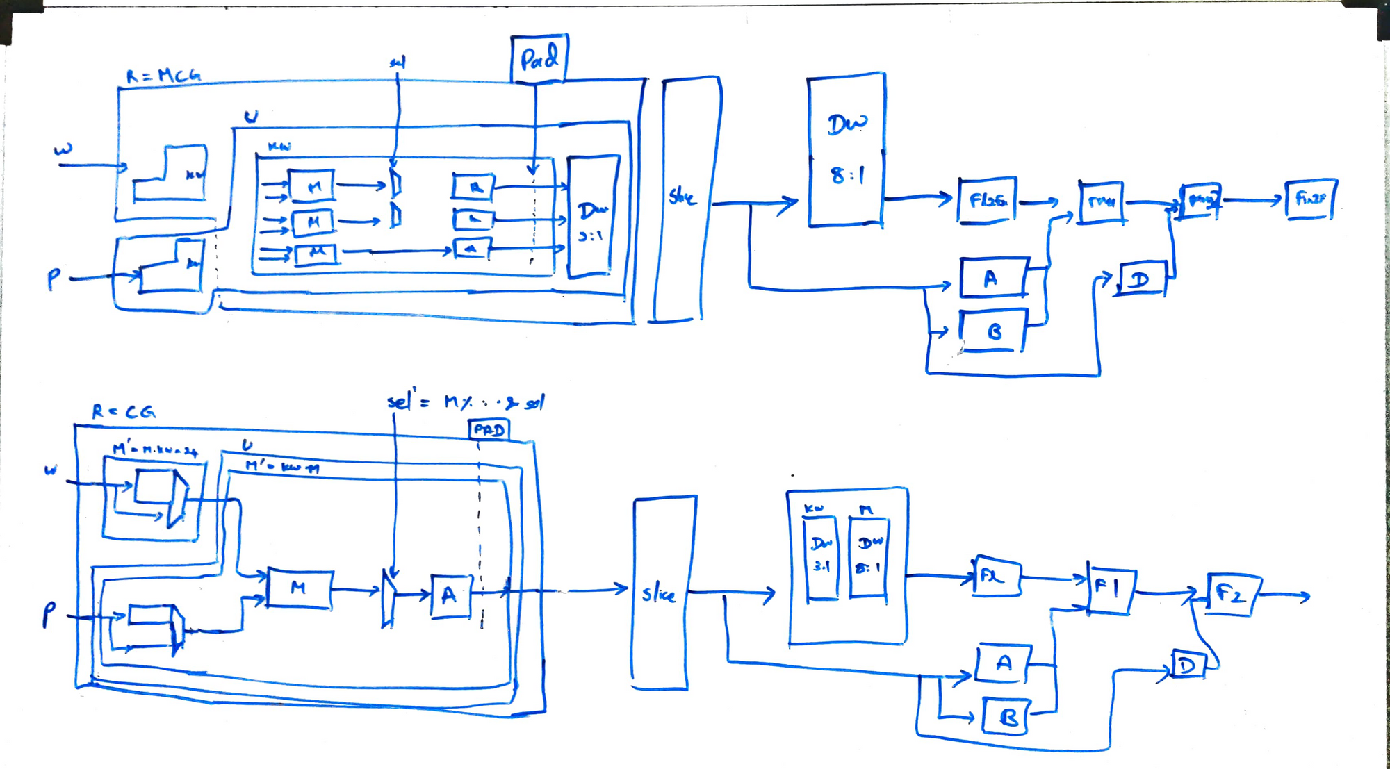
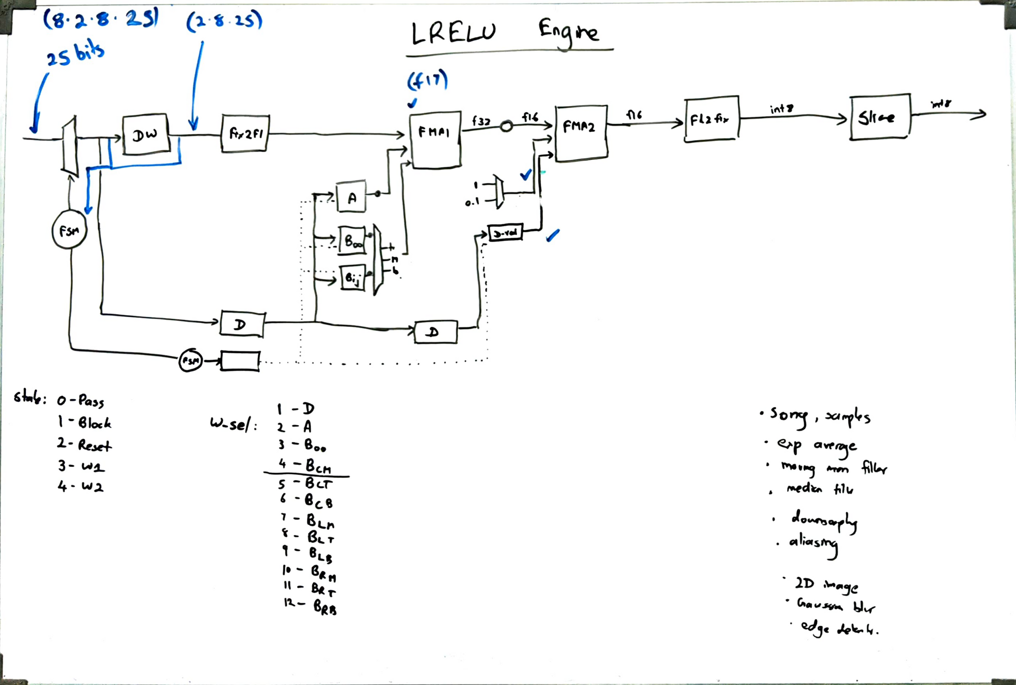
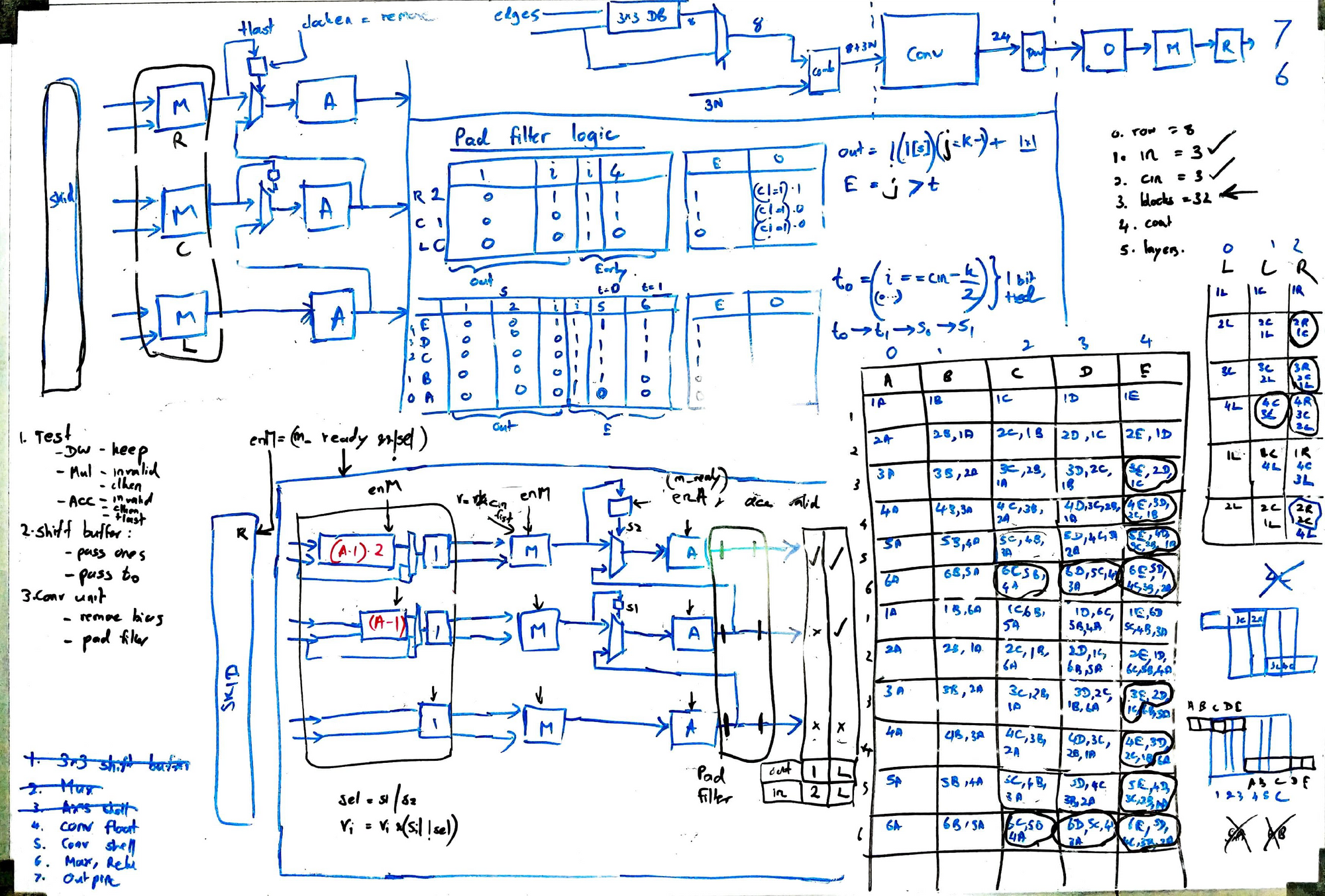
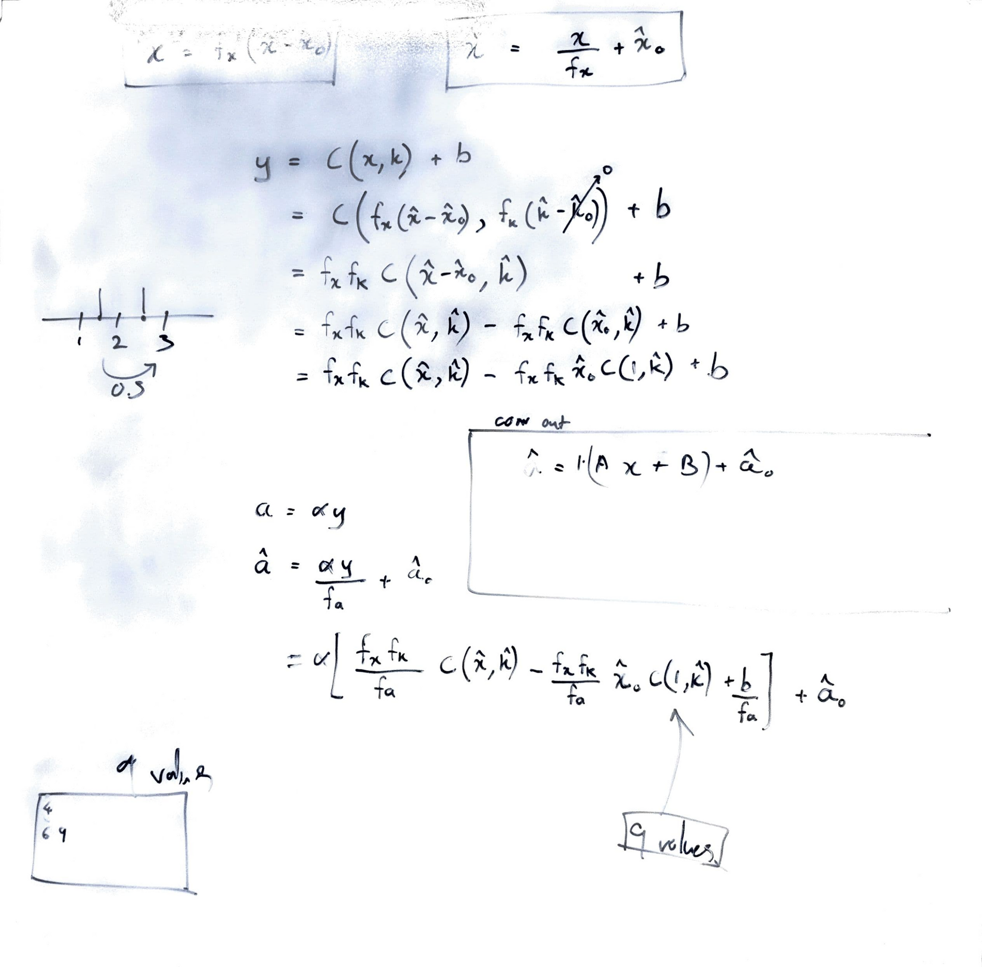
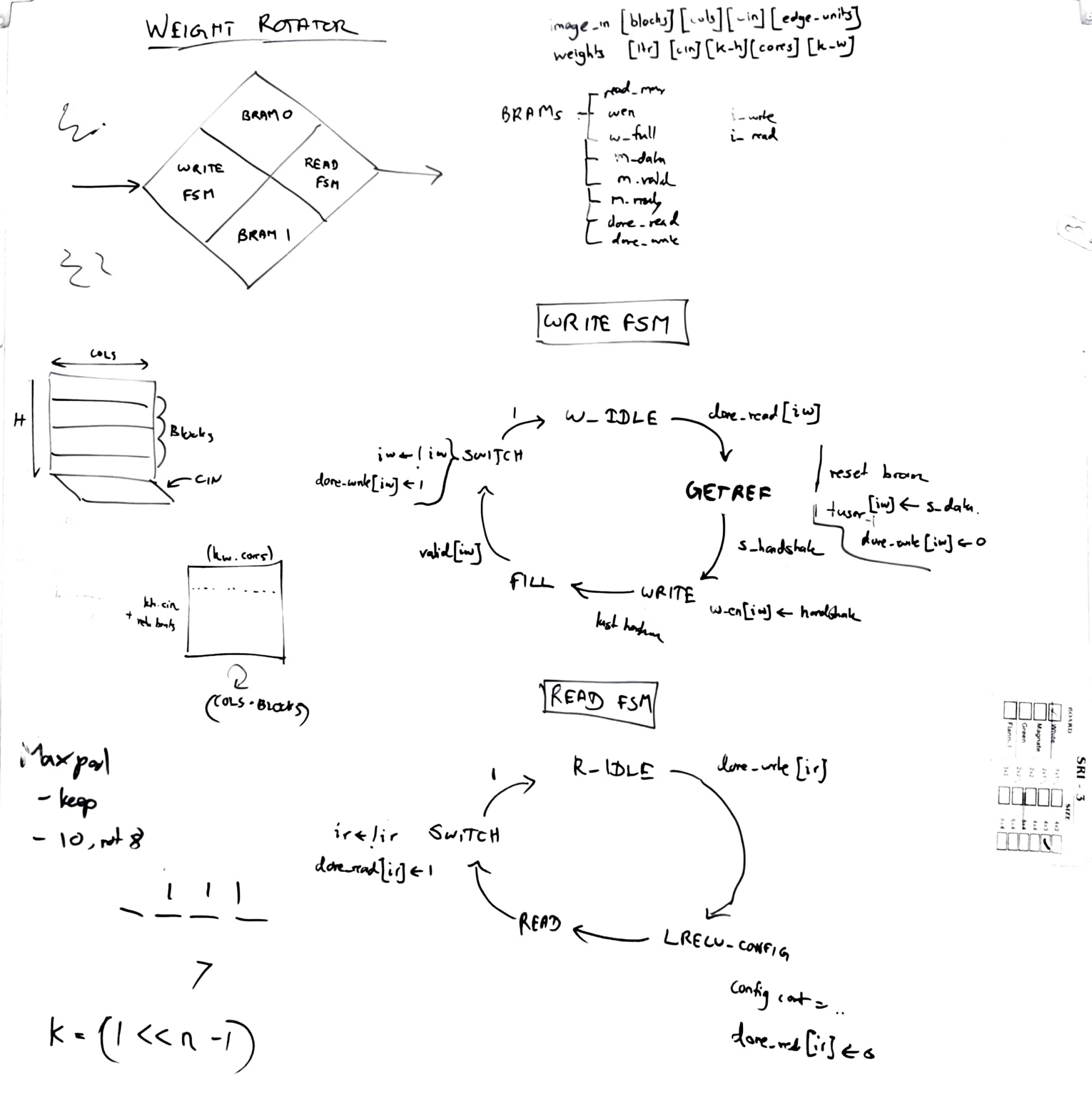
I almost always design my modules fully on a whiteboard before sitting down to write RTL. This helps to map out almost every register and multiplexer, get an idea of the critical paths, and also to reduce bugs.
4. RTL Design
SystemVerilog / Verilog
I then start writing modules, state-machines...etc. using synthesizable SystemVerilog, converting my whiteboard drawings into code. This is fairly straightforward. I've given a stripped-down example code of my conv engine. The key things to note are:
- SystemVerilog - Verilog lacks a lot of features and has the potential to cause serious bugs. SystemVerilog is beautiful and a breeze to write and read.
- Multidimensional wires and ports - I use them a lot, to group ports meaningfully and connect with each other. I prefer packed over unpacked, so multidimensional SystemVerilog ports can be seamlessly connected to Verilog wrappers with flat ports, without having to manually flatten them.
- Readability - I take this seriously. Order does not matter in HDL, but I write in a way that the code top to bottom corresponds to left to right in my whiteboard diagram (the way signal flows).
- Macro Parameters - I put all the parameters, derived parameters in a common file and include it in all modules. That file itself is written through a tcl script. This way, the parameters of all files are guaranteed to be the same, avoiding bugs and also making the code readable.
- No always@clk: This might be a surprise. In my entire synthesizable codebase of 9000 lines, I have only one sequential always block: in a parametrized module named register.v. The register module has optional clken, different types of reset...etc. All other modules instantiate this whenever needed. This helps me to avoid bugs, and to visualize the signal flow, as it directly translates from my whiteboard to code.
- FPGA & ASIC - Using preprocessor directives (`ifdef), I write code to suit both FPGA and ASIC. Registers have async reset in ASIC mode and sync reset in FPGA mode.
`timescale 1ns/1ps
`include "../include/params.v"

module conv_engine #(ZERO=0) (
    clk            ,
    clken          ,
    resetn         ,
    s_valid        ,
    s_ready        ,
    s_last         ,
    s_user         ,
    s_data_pixels  ,
    s_data_weights ,
    m_valid        ,
    m_data         ,
    m_last         ,
    m_user
  );
  input  logic clk, clken, resetn;
  input  logic s_valid, s_last;
  output logic s_ready;
  output logic m_valid, m_last;
  input  logic [`TUSER_WIDTH_CONV_IN-1:0] s_user;
  input  logic [`COPIES-1:0][`UNITS -1:0]                          [`WORD_WIDTH_IN    -1:0] s_data_pixels;
  input  logic [`COPIES-1:0][`GROUPS-1:0][`MEMBERS-1:0]            [`WORD_WIDTH_IN    -1:0] s_data_weights;
  output logic [`COPIES-1:0][`GROUPS-1:0][`MEMBERS-1:0][`UNITS-1:0][`WORD_WIDTH_OUT   -1:0] m_data;
  output logic [`TUSER_WIDTH_CONV_OUT-1:0] m_user;

  // Code ommited
  logic [`KW_MAX/2:0][`SW_MAX -1:0][`MEMBERS -1:0] lut_sum_start;
  logic [`COPIES-1:0][`GROUPS-1:0][`MEMBERS-1:0][`UNITS-1:0][`WORD_WIDTH_IN*2-1:0] mul_m_data ;
  logic [`COPIES-1:0][`GROUPS-1:0][`MEMBERS-1:0][`UNITS-1:0][`WORD_WIDTH_OUT -1:0] acc_s_data ;
  logic [`COPIES-1:0][`GROUPS-1:0][`MEMBERS-1:0][`UNITS-1:0][`WORD_WIDTH_OUT -1:0] mux_s2_data;

  generate
    genvar c,g,u,m,b,kw2,sw_1;
    // Code ommitted
    for (c=0; c < `COPIES; c++)
      for (g=0; g < `GROUPS; g++)
        for (u=0; u < `UNITS; u++)
          for (m=0; m < `MEMBERS; m++)
            if (m==0) assign mux_s2_data [c][g][m][u] = 0;
            else      assign mux_s2_data [c][g][m][u] = m_data     [c][g][m-1][u];
    assign mux_sel_next = mul_m_valid && mul_m_user[`I_IS_CIN_LAST] && (mul_m_kw2 != 0);

    register #(
      .WORD_WIDTH     (1),
      .RESET_VALUE    (0)
    ) MUX_SEL (
      .clock          (clk   ),
      .resetn         (resetn),
      .clock_enable   (clken ),
      .data_in        (mux_sel_next),
      .data_out       (mux_sel )
    );
    assign clken_mul = clken && !mux_sel;

    for (m=0; m < `MEMBERS; m++) begin: Mb
      for (kw2=0; kw2 <= `KW_MAX/2; kw2++)
        for (sw_1=0; sw_1 < `SW_MAX; sw_1++) begin
          localparam k = kw2*2 + 1;
          localparam s = sw_1 + 1;
          localparam j = k + s -1;

          assign lut_sum_start[kw2][sw_1][m] = m % j < s; // m % 3 < 1 : 0,1
        end
      assign acc_m_sum_start [m] = lut_sum_start[acc_m_kw2][acc_m_sw_1][m] & acc_m_user[`I_IS_SUM_START];
      // Code ommited
    end

    for (c=0; c < `COPIES; c++) begin: Ca
      for (g=0; g < `GROUPS; g++) begin: Ga
        for (u=0; u < `UNITS; u++) begin: Ua
          for (m=0; m < `MEMBERS; m++) begin: Ma
            processing_element PROCESSING_ELEMENT (
              .clk           (clk           ),
              .clken         (clken         ),
              .resetn        (resetn        ),
              .clken_mul     (clken_mul     ),
              .s_data_pixels (s_data_pixels [c]      [u]),
              .s_data_weights(s_data_weights[c][g][m]   ),
              .mul_m_data    (mul_m_data    [c][g][m][u]),
              .mux_sel       (mux_sel       ),
              .mux_s2_data   (mux_s2_data   [c][g][m][u]),
              .bypass        (bypass        [m]),
              .clken_acc     (clken_acc     [m]),
              .acc_s_data    (acc_s_data    [c][g][m][u]),
              .m_data        (m_data        [c][g][m][u])
            );
    end end end end

    // Code ommitted
    assign m_user_base[`I_IS_BOTTOM_BLOCK:`I_IS_NOT_MAX] = acc_m_user[`I_IS_BOTTOM_BLOCK:`I_IS_NOT_MAX];
    assign m_user  = {m_clr, m_shift_b, m_shift_a, m_user_base};
  endgenerate
endmodule
module processing_element (
clk ,
clken ,
resetn ,
clken_mul,
s_data_pixels,
s_data_weights,
mul_m_data,
mux_sel,
mux_s2_data,
bypass,
clken_acc,
acc_s_data,
m_data
);
input logic clk, clken, resetn;
input logic clken_mul, mux_sel, bypass, clken_acc;
input logic [`WORD_WIDTH_IN -1:0] s_data_pixels, s_data_weights;
input logic [`WORD_WIDTH_OUT -1:0] mux_s2_data;
output logic [`WORD_WIDTH_IN*2-1:0] mul_m_data;
output logic [`WORD_WIDTH_OUT -1:0] acc_s_data;
output logic [`WORD_WIDTH_OUT -1:0] m_data;
`ifdef MAC_XILINX
multiplier MUL (
`else
multiplier_raw MUL (
`endif
.CLK (clk),
.CE (clken_mul),
.A (s_data_pixels ),
.B (s_data_weights),
.P (mul_m_data )
);
assign acc_s_data = mux_sel ? mux_s2_data : `WORD_WIDTH_OUT'(signed'(mul_m_data));
`ifdef MAC_XILINX
accumulator ACC (
`else
accumulator_raw ACC (
`endif
.CLK (clk),
.bypass (bypass ),
.CE (clken_acc ),
.B (acc_s_data ),
.Q (m_data )
);
endmodule5. Test Vector Generation
Python
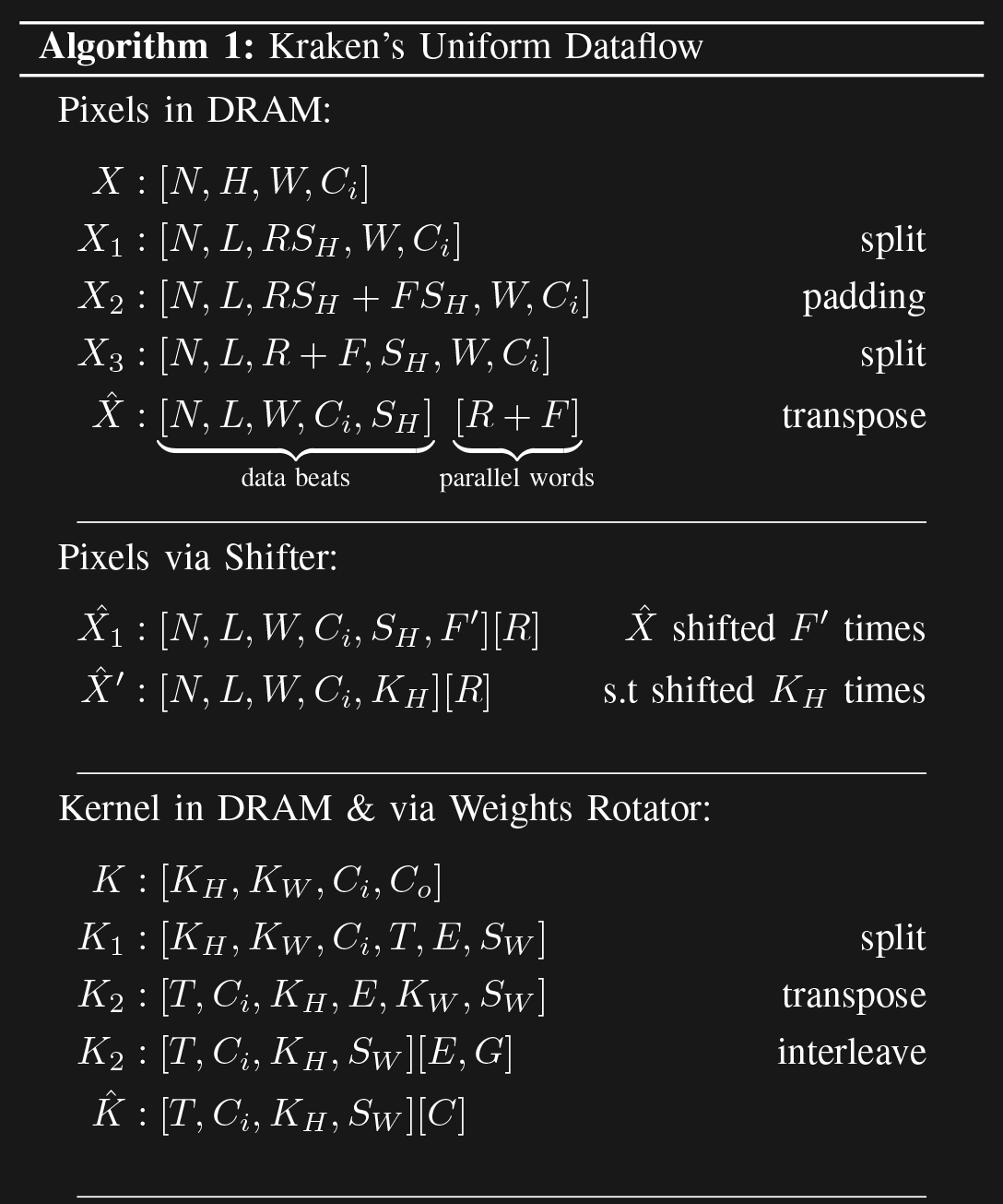
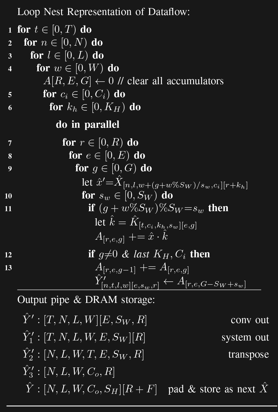
Next, I write python functions to extracts weights and inputs of each layer from my custom framework model (2.2), and convert them into input test vectors. Their dimensions need to be split, reshaped, transposed and flattened to get the final input \(\hat{X}\), and weights \(\hat{K}\) packets which can be understood by the hardware I designed. Output \(\hat{Y}\) is also transformed to match the hardware's outputs. Also, configuration bits need to be calculated and appended to the packet to make it complete.
def get_weights(i_layers, i_itr, c):
    weights = c.LAYERS[f'{c.PREFIX_CONV}{i_layers}'].weights
    KH, KW, CIN, COUT = weights.shape
    max_factor = 2 if f'{c.PREFIX_MAX}{i_layers}' in c.LAYERS.keys() else 1
    print(f"get_weights - shape_in:(KH, KW, CIN, COUT) = {weights.shape}")

    '''
    Reshape
    '''
    weights = weights.transpose(3,0,1,2) #(COUT,KH,KW,CIN)
    weights = fill_invalid_scg(weights,KW=KW,max_factor=max_factor,c=c) #(ITR,EFF_CORES,KH,KW,CIN)
    ITR,EFF_CORES = weights.shape[0:2]
    weights = weights.transpose(0,4,2,1,3) #(ITR,CIN,KH,EFF_CORES,KW)

    '''
    * Data comes out of maxpool in the order: S,CGU
    * Data comes out of conv in the order   : CGMU and is transposed into S,CGUby hardware
    * Conv in takes weights in order        : CGM

    * Since system_out is SCG, first invalid should be filled that way, so that output data is continous and cin matches cout
    * After filling, we transpose it to CGM
    '''
    SUB_CORES = c.MEMBERS//KW
    weights = weights.reshape((ITR,CIN,KH, SUB_CORES,c.COPIES//max_factor,c.GROUPS ,KW)) # EFF_CORES = (SCG)
    weights = weights.transpose(0,1,2, 4,5, 3,6) # CGS
    weights = weights.reshape((ITR,CIN,KH,1,c.COPIES//max_factor,c.GROUPS,SUB_CORES,KW)) # (CGS)
    weights = np.repeat(weights,repeats=max_factor,axis=3)
    weights = weights.reshape((ITR,CIN,KH,c.COPIES,c.GROUPS,SUB_CORES,KW))
    weights = weights.reshape((ITR,CIN,KH,c.COPIES,c.GROUPS,SUB_CORES*KW))
    zeros = np.zeros((ITR,CIN,KH,c.COPIES,c.GROUPS,c.MEMBERS), dtype=weights.dtype)
    zeros[:,:,:,:,:,0:SUB_CORES*KW] = weights
    weights = zeros

    KERNEL_BEATS = CIN*KH
    weights = weights.reshape(ITR,KERNEL_BEATS,c.COPIES,c.GROUPS,c.MEMBERS)

    '''
    Add LRELU Beats
    '''
    lrelu = get_lrelu_config(i_layers=i_layers,c=c)

    LRELU_BEATS = lrelu.shape[1]
    weights_beats = np.concatenate([lrelu,weights], axis=1) # (ITR, LRELU_BEATS + KERNEL_BEATS, COPIES, GROUPS, MEMBERS)

    _,H,W,CIN = c.LAYERS[f'{c.PREFIX_CONV}{i_layers}'].in_data.shape
    BLOCKS    = H // (SH*max_factor*c.CONV_UNITS)

    bram_weights_addr_max = LRELU_BEATS + SW*KH*CIN-1
    print("bram_weights_addr_max: ", bram_weights_addr_max)

    weights_config = 0
    weights_config |= (KW//2)
    weights_config |= (KH//2)               << (BITS_KW2)
    weights_config |= SW-1                  << (BITS_KW2 + BITS_KH2)
    weights_config |= (CIN   -1)            << (BITS_KW2 + BITS_KH2 + BITS_SW)
    weights_config |= (W     -1)            << (BITS_KW2 + BITS_KH2 + BITS_SW + BITS_CIN_MAX)
    weights_config |= (BLOCKS-1)            << (BITS_KW2 + BITS_KH2 + BITS_SW + BITS_CIN_MAX + BITS_COLS_MAX)
    weights_config |= bram_weights_addr_max << (BITS_KW2 + BITS_KH2 + BITS_SW + BITS_CIN_MAX + BITS_COLS_MAX + BITS_BLOCKS_MAX)

    weights_config = np.frombuffer(np.uint64(weights_config).tobytes(),np.int8)
    weights_config = np.repeat(weights_config[np.newaxis,...],repeats=ITR,axis=0)

    '''
    ADD c BEATS
    '''
    weights_dma_beats = np.concatenate([weights_config,weights_beats.reshape(ITR,-1)], axis=1)

    assert weights_dma_beats.shape == (ITR, 8 + (LRELU_BEATS + CIN*KH*SW)*c.COPIES*c.GROUPS*c.MEMBERS)
    print(f"get_weights - weights_dma_beats.shape: (ITR, 4 + (LRELU_BEATS + CIN*KH)*COPIES*GROUPS*MEMBERS) = {weights_dma_beats.shape}")

    np.savetxt(f"{c.DATA_DIR}{i_layers}_weights.txt", weights_dma_beats[i_itr].flatten(), fmt='%d')
    return weights_dma_beats
6. Testbench & Simulation
SystemVerilog
Next, I write testbenches for the modules. They are built around two custom SystemVerilog classes: AXIS_Slave, which reads a text file and loads data into an AXI stream port while conforming to the protocol, and AXIS_Master which reads data from a port and writes into a text file.
The control signals: valid and ready are randomized. They get toggled according to a given probability, to simulate the effects of memory bus freezing up and clearing.
`timescale 1ns/1ps
class AXIS_Slave #(WORD_WIDTH=8, WORDS_PER_BEAT=1, VALID_PROB=100);

  string file_path;
  int words_per_packet, status, iterations, i_words;
  int file = 0;
  int i_itr = 0;
  bit enable = 0;
  bit first_beat = 1;

  rand bit s_valid;
  constraint c { s_valid dist { 0 := (100-VALID_PROB), 1 := (VALID_PROB)}; };

  function new(string file_path, int words_per_packet, int iterations);
    this.file_path = file_path;
    this.words_per_packet = words_per_packet;
    this.iterations = iterations;
    this.file = $fopen(this.file_path, "r");
  endfunction

  function void fill_beat(
    ref logic [WORDS_PER_BEAT-1:0][WORD_WIDTH-1:0] s_data,
    ref logic [WORDS_PER_BEAT-1:0] s_keep,
    ref logic s_last);

    if($feof(file)) $fatal(1, "EOF found\n");
    if (first_beat) first_beat = 0;

    for (int i=0; i < WORDS_PER_BEAT; i++) begin
      status = $fscanf(file,"%d\n", s_data[i]);
      s_keep[i] = i_words < words_per_packet;
      i_words  += 1;
    end
    if(i_words >= words_per_packet)
      s_last = 1;
  endfunction

  function void reset(
    ref logic s_valid,
    ref logic [WORDS_PER_BEAT-1:0][WORD_WIDTH-1:0] s_data,
    ref logic [WORDS_PER_BEAT-1:0] s_keep,
    ref logic s_last
  );
    enable = 0;
    s_data = '{default:0};
    s_valid = 0;
    s_keep = 0;
    s_last = 0;
    first_beat = 1;
    i_words = 0;

    if (file != 0) $fclose(file);
    file = $fopen(file_path, "r");
  endfunction

  task axis_feed(
    ref logic aclk,
    ref logic s_ready,
    ref logic s_valid,
    ref logic [WORDS_PER_BEAT-1:0][WORD_WIDTH-1:0] s_data,
    ref logic [WORDS_PER_BEAT-1:0] s_keep,
    ref logic s_last
  );
    // Before beginning: set all signals zero
    if (~enable) begin
      this.reset(s_valid, s_data, s_keep, s_last);
      @(posedge aclk);
      return;
    end

    @(posedge aclk);
    this.randomize(); // random this.s_valid at every cycle
    if (s_ready && (first_beat ? this.s_valid : s_valid)) begin
      // If s_last has passed with handshake, packet done. start next itr
      if(s_last) begin #1;
        i_itr += 1;
        this.reset(s_valid, s_data, s_keep, s_last);

        if (i_itr < iterations)
          enable = 1;
        else begin
          $fclose(file);
          return;
        end
      end
      else #1;

      // If file is not open, keep valid down.
      if(file == 0) begin
        s_valid = 0;
        return;
      end
      else this.fill_beat(s_data, s_keep, s_last);
    end
    else #1;

    if (~first_beat) s_valid = this.s_valid;
  endtask
endclassFollowing is an example on how AXIS slave and master classes are utilized. Each module gets a testbench like this. Some modules get multiple slave and multiple masters.
module axis_tb_demo();
timeunit 1ns;
timeprecision 1ps;
localparam CLK_PERIOD = 10;
logic aclk;
initial begin
aclk = 0;
forever #(CLK_PERIOD/2) aclk <= ~aclk;
end
localparam WORD_WIDTH = 8;
localparam WORDS_PER_PACKET = 40;
localparam WORDS_PER_BEAT = 4;
localparam ITERATIONS = 6;
localparam BEATS = int'($ceil(real'(WORDS_PER_PACKET)/real'(WORDS_PER_BEAT)));
logic [WORDS_PER_BEAT -1:0][WORD_WIDTH-1:0] data;
logic [WORDS_PER_BEAT -1:0] keep;
logic valid, ready, last;
string path = "D:/cnn-fpga/data/axis_test.txt";
string out_base = "D:/cnn-fpga/data/axis_test_out_";
AXIS_Slave #(
.WORD_WIDTH (WORD_WIDTH ),
.WORDS_PER_BEAT(WORDS_PER_BEAT),
.VALID_PROB (70 )
) slave_obj = new(
.file_path (path),
.words_per_packet(WORDS_PER_PACKET),
.iterations (ITERATIONS)
);
AXIS_Master #(
.WORD_WIDTH (WORD_WIDTH ),
.WORDS_PER_BEAT(WORDS_PER_BEAT),
.READY_PROB (70 ),
.CLK_PERIOD (CLK_PERIOD ),
.IS_ACTIVE (1 )
) master_obj = new(
.file_base(out_base),
.words_per_packet(-1),
.packets_per_file(2)
);
initial forever slave_obj.axis_feed(aclk, ready, valid, data, keep, last);
initial forever master_obj.axis_read(aclk, ready, valid, data, keep, last);
initial begin
@(posedge aclk);
slave_obj.enable <= 1;
master_obj.enable <= 1;
end
int s_words, s_itr, m_words, m_itr, m_packets, m_packets_per_file;
initial
forever begin
@(posedge aclk);
s_words = slave_obj.i_words;
s_itr = slave_obj.i_itr;
m_words = master_obj.i_words;
m_itr = master_obj.i_itr;
m_packets = master_obj.i_packets;
m_packets_per_file = master_obj.packets_per_file;
end
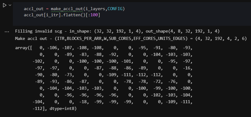
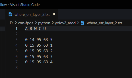
endmodule7. Debugging
Python Notebooks & SystemVerilog Simulations
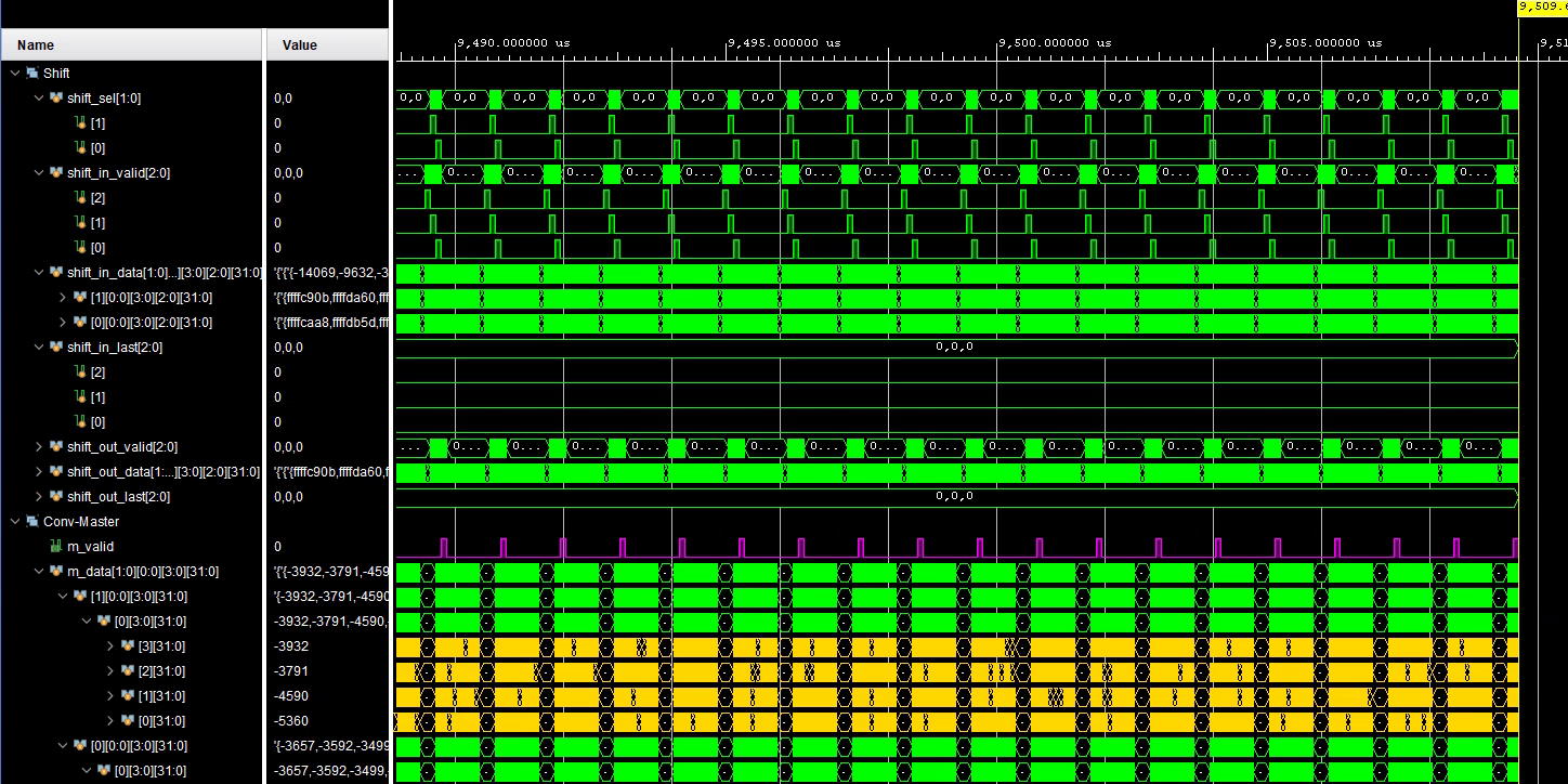
I then run simulations, collect output vectors and compare them with expected vectors using python notebooks. Notebooks allow one to play around with data, quickly print and observe different dimensions...etc.
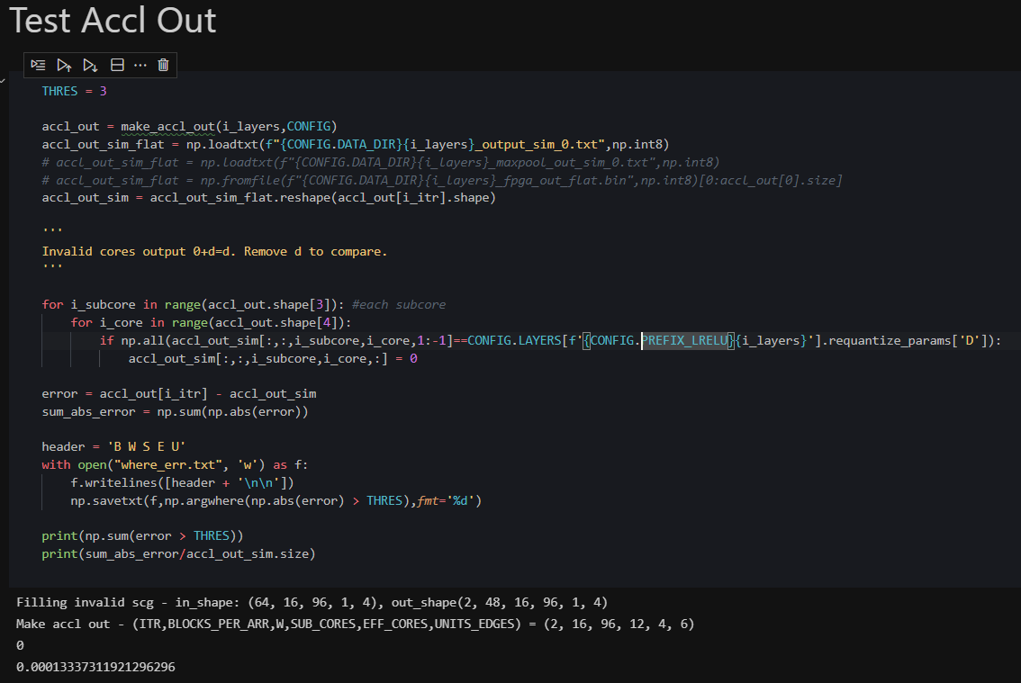
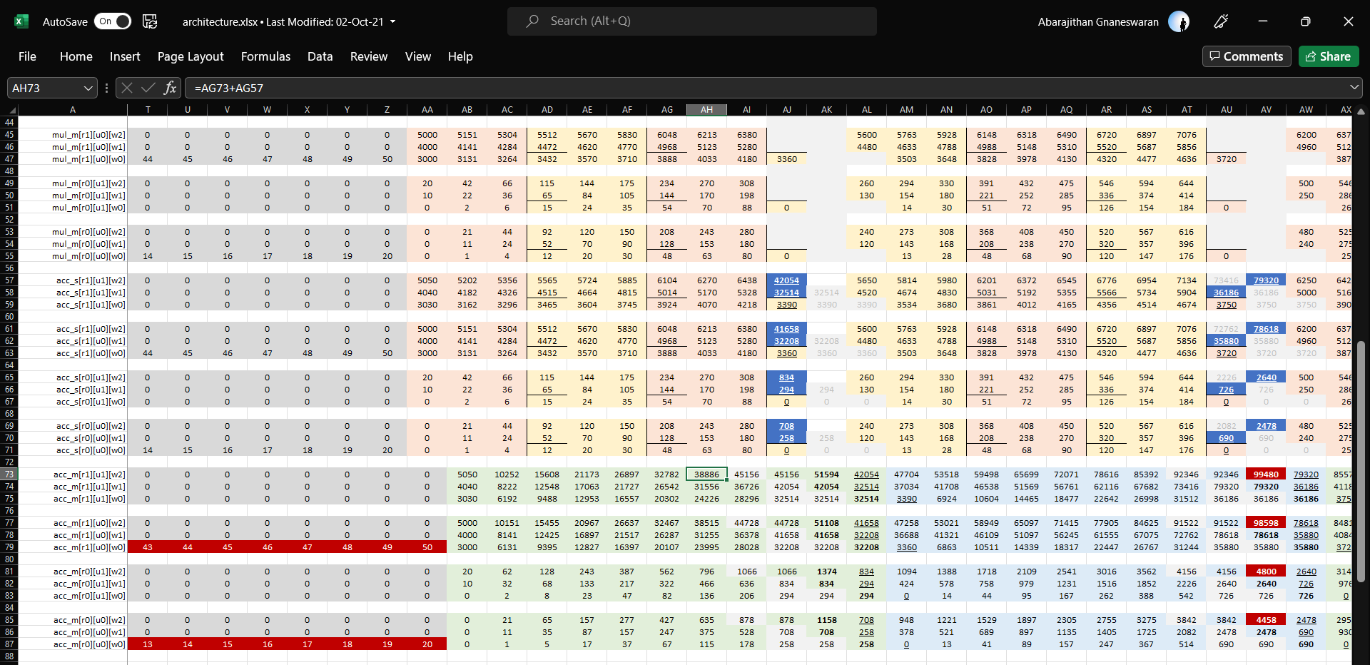
8. Debugging with Microsoft Excel
Yep :-)
In some cases, the output from a module is garbage and does not match the expected output at all. Since it is a convolution over several values, it is near impossible to guess the bug by looking at such garbage numbers. In that case, I resort to Excel, where I manually transform a set of small input vectors through the logic, step by step to see what I should expect in every clock cycle. I then compare it to the waveforms I see in the simulator to figure out where the bug is.
9. Repeat
I move back and forth between the whiteboard, RTL code, python code, and simulation to fix bugs one by one. Some take weeks and make me want to pull my hair out. I also do this for each module, then put them together hierarchically, write integration testbenches, and test that too.
10. ASIC Synthesis
Once the design is verified in randomized simulations, I write the scripts for ASIC synthesis. Our university uses Cadence tools, so the following script is for Cadence Genus, using 65nm CMOS PDK from TSMC.
set TOP axis_accelerator_asic
# set TOP axis_conv_engine

#--------- CONFIG
set RTL_DIR ../../rtl
set XILINX 0
source ../../tcl/config.tcl
set_db hdl_max_loop_limit 10000000

set TECH 65nm
set NUM_MACS [expr $MEMBERS*$UNITS*$GROUPS*$COPIES]
set REPORT_DIR ../report/${TECH}/${TOP}/${NUM_MACS}
exec mkdir -p $REPORT_DIR

#--------- LIBRARIES
set LIB_DIR ../../../tsmc/${TECH}/GP
set_db library [glob $LIB_DIR/cc_lib/noise_scadv10_cln65gp_hvt_tt_1p0v_25c.lib $LIB_DIR/cc_lib/scadv10_cln65gp_hvt_tt_1p0v_25c.lib]
set_db lef_library [glob $LIB_DIR/lef/tsmc_cln65_a10_6X1Z_tech.lef $LIB_DIR/lef/tsmc_cln65_a10_6X2Z_tech.lef $LIB_DIR/lef/tsmc65_hvt_sc_adv10_macro.lef]
set_db qrc_tech_file $LIB_DIR/other/icecaps.tch
# set LIB_DIR ../../../tsmc/${TECH}/LP
# set_db library [glob $LIB_DIR/lib/sc12_cln65lp_base_hvt_tt_typical_max_1p00v_25c.lib $LIB_DIR/lib/sc12_cln65lp_base_hvt_tt_typical_max_1p20v_25c.lib]
# set_db lef_library [glob $LIB_DIR/lef/sc12_cln65lp_base_hvt.lef]

#--------- READ
read_hdl -mixvlog [glob $RTL_DIR/include/*]
read_hdl -mixvlog [glob $RTL_DIR/external/*]
read_hdl -mixvlog [glob $RTL_DIR/src/*]

#--------- ELABORATE & CHECK
set_db lp_insert_clock_gating true
elaborate $TOP
check_design > ${REPORT_DIR}/check_design.log
uniquify $TOP

#--------- CONSTRAINTS
set PERIOD [expr 1000.0/$FREQ_HIGH]
create_clock -name aclk -period $PERIOD [get_ports aclk]
set_dont_touch_network [all_clocks]
set_dont_touch_network [get_ports {aresetn}]

set design_inputs [get_ports {m_axis_tready s_axis_pixels_tvalid s_axis_pixels_tlast s_axis_pixels_tdata s_axis_pixels_tkeep s_axis_weights_tvalid s_axis_weights_tlast s_axis_weights_tdata s_axis_weights_tkeep}]
set design_outputs [get_ports {s_axis_pixels_tready  s_axis_weights_tready m_axis_tvalid m_axis_tlast m_axis_tdata m_axis_tkeep}]

set_input_delay  [expr $PERIOD * 0.6] -clock aclk $design_inputs
set_output_delay [expr $PERIOD * 0.6] -clock aclk $design_outputs

#--------- RETIME OPTIONS
set_db retime_async_reset true
set_db design:${TOP} .retime true

#--------- SYNTHESIZE
set_db syn_global_effort high
syn_generic
syn_map
syn_opt

#--------- NETLIST
write -mapped > ../output/${TOP}.v
write_sdc > ../output/${TOP}.sdc

#--------- REPORTS
report_area > ${REPORT_DIR}/area.log
report_gates > ${REPORT_DIR}/gates.log
report_timing  -nworst 10 > ${REPORT_DIR}/timing.log
report_congestion > ${REPORT_DIR}/congestion.log
report_messages > ${REPORT_DIR}/messages.log
report_hierarchy > ${REPORT_DIR}/hierarchy.log
report_clock_gating > ${REPORT_DIR}/clock_gating.log

build_rtl_power_models -clean_up_netlist
report_power > ${REPORT_DIR}/power.log
Next:
 Abarajithan G